| Power |
| Input Supply Voltage |
6 - 30 vDC, unregulated ( 12 vDC Nominal ) |
| Current |
0.29 amps |
| Power Consumption |
3.5 watts |
| Power Connector |
5.5mm x 9.5mm x 2.1mm barrel socket |
| Power Adapter |
| Universal AC/DC Adapter |
100-240v AC, regulated DC adapter included |
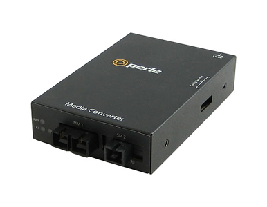
| Indicators |
| Power / TST |
This green LED is turned on when power is applied to the media converter. Otherwise it is off. The LED will blink slowly when in Loopback test mode. |
| Fiber link 1 / Receive activity (LK1) |
This green LED is operational only when power is applied. The LED is on when the 100Base-X link is on and flashes with a 50% duty cycle when data is received. |
| Fiber link 2 on / Receive activity (LK2) |
This green LED is operational only when power is applied. The LED is on when the 100Base-X link is on and flashes with a 50% duty cycle when data is received. |
| Switches - accessible through a side opening in the chassis |
| Link Pass Through |
Enabled (Default) - When the state of the receiver is changed on one of the 100Base-X interfaces it is reflected on the other 100Base-X fiber transmitter. If disabled, the 100Base-X fiber interfaces operate independently. Far-End Fault indication on the 100Base-FX fiber interface has no effect on the other interface. |
| Far-End Fault (FEF) |
Enabled ( default ) - The media converter transmits the Far-End Fault Indication over the fiber connection whenever a receive failure is detected. The media converter continuously monitors the fiber connection and clears the Far-End Fault Indication condition when a valid signal is received.
Enabled - The 100Base-X receiver is looped to the 100Base-X transmitter. Link #2's fiber transmitter is taken off the interface. |
| Remote Loopback #1 |
The media converter can perform a loopback on the link #1 fiber interface.
Disabled (Default - Up)
Enabled - The 100Base-X receiver is looped to the 100Base-X transmitter. The 100Base-TX transmitter is taken off the interface. |
| Remote Loopback #2 |
The media converter can perform a loopback on the link #1 fiber interface.
Disabled (Default - Up)
Enabled - The 100Base-X receiver is looped to the 100Base-X transmitter. Link #1's fiber transmitter is taken off the interface. |
| Cables |
| Fiber Optic Cable |
Multimode dual SC [ 2 km/1.2 ] to single single SC fiber connector model
Multimode: 62.5 / 125, 50/125, 85/125, 100/140 micron
Single Mode: 9/125 micron (ITu-T 625) |
| Packet Transmission Characteristics |
| Bit Error Rate (BER) |
<10 -12 |
| Environmental Specifications |
| Operating Temperature |
0 C to 50 C (32 F to 122 F) |
| Storage Temperature |
minimum range of -25 C to 70 C (-13 F to 158 F) |
| Operating Humidity |
5% to 90% non-condensing |
| Storage Humidity |
5% to 95% non-condensing |
| Operating Altitude |
Up to 3,048 meters (10,000 feet) |
Heat Output
( BTU/HR ) |
11.9 |
| MTBF (Hours)** |
Without power adaptor: 503,679
With power adaptor: 302,090 |
| Mounting |
| Din Rail Kit |
Optional |
| Rack Mount Kit |
Optional |
| Product Weight and Dimensions |
| Weight |
0.3 kg, 0.66 lbs |
| Dimensions |
120 x 80 x 26 mm, 4.7 x 3.1 x 1.0 inches |
| Packaging |
| Shipping Weight |
0.55 kg, 1.2 lbs |
| Shipping Dimensions |
170 x 280 x 70 mm, 6.7 x 10.2 x 2.8 inches |
| Regulatory Approvals |
| Emissions |
FCC Part 15 Class B*, EN55022 Class B* |
| CISPR 22 Class B* |
| EN61000-3-2 |
| Immunity |
EN55024 |
| Electrical Safety |
UL 60950-1 |
| EN60950 |
| CE |
| Laser Safety |
EN 60825-1:2007 |
| Fiber optic transmitters on this device meet Class 1 Laser safety requirements per IEC-60825 FDA/CDRH standards and comply with 21CFR1040.10 and 21CFR1040.11. |
| Environmental |
Reach, RoHS and WEEE Compliant |
| Other |
ECCN: 5A991A |
| HTSUS Number: 8517.62.0050 |
| Perle Limited Lifetime Warranty |