|
Local ( power over link - VDSL ) |
| Power |
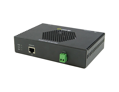
eXP-1S1110L |
| Unit Powered by |
- Local power adapter or
- PoE Power Sourcing Equipment such as a Cisco PoE+ Switch on port #1
- PoE+ power injector
|
| Provides Power to: |
Link ( VDSL Interlink ) |
| Power adapter connector |
Barrel or terminal block |
| Input Voltage Range from adapter |
29 to 57 |
| Input Voltage Range from VDSL (parasitic) |
N/A |
| Universal AC Adapter |
48vDC, 60 watts is included when purchased an individual basis.
One 48vDC 60 watts adapter is provided in each kit. |
| Power Connectors |
5.5mm x 9.5mm x 2.1mm barrel socket and 2 pin terminal Block |
|
Local ( power over link - VDSL ) |
| Ethernet |
eXP-1S1110L |
| 10/100/1000Base-T Port(s) |
1 port RJ45 Shielded |
| Auto-MDIX |
Auto-MDIX enables proper operation with either straight-through or crossover cabling |
| Distance |
Distance up to 100 meters ( 328 feet ) as per IEEE 802.3 |
| Maximum Frame Size |
1522 |
| Type of PoE device |
PD ( Class 0 or 4 device ) |
| PoE PSE Maximum Power (Watts) |
N/A |
| PoE PSE RJ45 Cable Pinout |
N/A |
|
Local ( power over link - VDSL ) |
| VDSL – Interlink |
eXP-1S1110L |
| Connector |
Choice of RJ45, BNC or terminal block models for VDSL link connector
- RJ45 – RING pin 4, TIP pin 5 (TIA 568 A/B)
- BNC – Coaxial 75 ohm cable with BNC connector
- Terminal Block – 2 position screw connectors for use with twisted pair telephone, alarm or serial cabling
|
| Copper Cabling |
Ethernet Extenders must be connected in pairs using unconditioned wire between 19 ( 0.9 mm ) and 26 AWG ( 0.44 mm ). Circuits that run through signal equalization equipment are not permitted. |
| Power Injection over the Interlink ( VDSL ) – 2-wire |
Injects SELV compliant voltage and VDSL data across a single pair of cooper wires ( pins 4 and 5 ) or 2 conductor BNC coaxial cable |
| Short Circuit Protection |
Short Circuit protection provided |
| Reverse Polarity Protection |
N/A |
| Power Multiplier Selection |
When used with 4-pair cable such as CAT5 on the VDSL Interlink port, an optional internal strap selection on the Ethernet Extender will provide VDSL transmission data on 1 pair and power across the 3 other pairs enabling even greater distances for power transmission to be achieved |
| VDSL Line Rate/Reach |
Actual distance and rates experienced will depend on condition and gauge of wire used. This Rate/Reach table applies to 24 AWG ( 0.5 MM ) twisted pair wiring on RJ45 (RJ) and terminal block (TB) models.
| High Speed Asymmetric |
| Reach ( Distance ) |
VDSL Rate ( Mbps ) |
| feet |
meters |
Downstream |
Upstream |
| 500 |
152 |
101 |
92 |
| 1000 |
305 |
101 |
63 |
| 1500 |
457 |
90 |
38 |
| 2000 |
610 |
62 |
24 |
| 2500 |
762 |
55 |
10 |
| 3000 |
914 |
42 |
5 |
| 3500 |
1000 |
35 |
3 |
| High Speed Symmetric |
| Reach ( Distance ) |
VDSL Rate ( Mbps ) |
| feet |
meters |
Downstream |
Upstream |
| 500 |
152 |
101 |
101 |
| 1000 |
305 |
85 |
101 |
| 1500 |
457 |
62 |
47 |
| 2000 |
610 |
60 |
29 |
| 2500 |
762 |
44 |
14 |
| 3000 |
914 |
30 |
7 |
| 3500 |
1000 |
29 |
4 |
| Long Reach Symmetric |
| Reach ( Distance ) |
VDSL Rate ( Mbps ) |
| feet |
meters |
Downstream |
Upstream |
| 500 |
152 |
53 |
44 |
| 1000 |
305 |
53 |
43 |
| 2500 |
762 |
39 |
18 |
| 4000 |
1219 |
25 |
4 |
| 5500 |
1676 |
17 |
1.9 |
| 7000 |
2134 |
8 |
2.3 |
| 7500 |
2286 |
7 |
2.2 |
| 8000 |
2438 |
5 |
2.2 |
| Long Reach Asymmetric |
| Reach ( Distance ) |
VDSL Rate ( Mbps ) |
| feet |
meters |
Downstream |
Upstream |
| 500 |
152 |
78 |
16 |
| 1000 |
305 |
78 |
16 |
| 2500 |
762 |
55 |
10 |
| 4000 |
1219 |
31 |
0.8 |
| 5500 |
1676 |
20 |
0.6 |
| 7000 |
2134 |
11 |
0.6 |
| 7500 |
2286 |
10 |
0.6 |
| 8000 |
2438 |
8 |
0.6 |
This table applies when the power multiplier option is selected |
| Power Budget |
The amount of available power at the PoE PD is dependent on the scenario planned.
Refer to the Power Reach Installation Planning Guide |
|
Local ( power over link - VDSL ) |
| Indicators |
eXP-1S1110L |
| Power / TST |
This green LED is turned on when power is applied to the Ethernet Extender. Otherwise it is off. The LED will blink when in Loopback test mode. |
| CO - Local |
Ethernet Extender is operating in CO VDSL mode |
| CPE - remote |
Ethernet Extender is operating in CPE VDSL mode |
| ILNK |
Indicates Link Status and activity on the Interlink (VDSL) port |
| ETH |
Indicates link status and activity on Ethernet port(s). |
| PSE Status |
N/A |
|
Local ( power over link - VDSL ) |
| Switches |
eXP-1S1110L |
| Access |
Switch settings are accessible through a side opening in the chassis |
| Rate/Reach |
Two switches enable the user to select the right balance between speed and distance for their environment. |
| Signal to Noise Ratio |
Selectable Signal to Noise Ratio (SNR) of 6dB or 9dB. The higher SNR number provides better impulse noise protection but lowers performance. |
| Auto-Negotiation (802.3u) control on Port 1 |
Enabled (Default) - The Ethernet Extender uses 802.3u Auto-negotiation on the 10/100/1000Base-T interface. It is set to advertise full duplex.
Disabled - The Ethernet Extender sets the port according to the position of the speed and duplex switches. |
| Force Ethernet Speed on Port 1 |
When Auto-Negotiation switch is disabled, a fixed speed can be forced on port 1 to
100 (Default) or 10 |
| Force Ethernet Duplex on Port 1 |
When Auto-Negotiation switch is disabled, Full or half Duplex can be forced on port 1 to
Full (Default) or Half |
| Link Mode |
Standard (Default) – The 10/100/1000Base-T link remains active independent of the state of the Ethernet link on its remote peer.
Link Pass-Through- state of the 10/100/1000Base-T Ethernet connection is “passed through” or propagated across the VDSL link to the 10/100/1000Base-T Ethernet link on its remote Ethernet Extender peer. |
| Interlink Fault Feedback |
Enabled – A loss of VDSL link will drop the 10/100/1000 Ethernet port on each end until the link recovers
Disabled ( Default ) - The state of the VDSL link is not propagated to the 10/100/1000Base-T port |
| Loopback |
Enabled – The VDSL interlink will perform a loopback function, retransmitting all received Ethernet frames back to its remote peer.
Disabled (Default - Up) |
| PoE PD Class selection |
( Internal strap ) for PoE PD classification type identification for attached IEEE 802.3at compliant PoE+ switch on port #1
Class 0 – PoE PD device - 0.44-12.94W ( Default )
Class 4 – PoE+ PD device 12.95 – 25.5W |
| PD Reset ( Port 1 ) |
N/A |
| Environmental Specifications |
eXP-1S1110L |
| Operating Temperature |
0 C to 50 C (32 F to 122 F) |
| Storage Temperature |
minimum range of -25 C to 70 C (-13 F to 158 F) |
| Operating Humidity |
5% to 90% non-condensing |
| Storage Humidity |
5% to 95% non-condensing |
| Operating Altitude |
Up to 3,048 meters (10,000 feet) |
| Current mA |
144 @ 48vdc |
| Unit Power Consumption watts |
6.9 |
Heat Output
( BTU/HR ) |
23.54 |
| MTBF with power adapter (Hours)** |
199,390 |
| MTBF without power adapter (Hours)** |
340,165 |
| Mounting |
eXP-1S1110L |
| Wall/Desk |
Standard |
| Din Rail Kit |
Optional |
| Rack Mount Kit |
Optional |
| Product Weight and Dimensions |
eXP-1S1110L |
| Weight |
0.58 Kg, 1.3 lbs |
| Dimensions |
163 x 116 x 37 mm, 6.4 x 4.6 x 1.46 inches |
| Packaging |
eXP-1S1110L |
| Shipping Weight |
1.27 Kg, 2.8 lbs |
| Shipping Dimensions |
20 x 30 x 7 cm, 7.9 x 11.8 x 2.8 inches |
| Regulatory Approvals |
eXP-1S1110L |
| Emissions |
EN 55022 |
| CISPR 22 |
| IEC/EN 61000-3-2 |
| IEC/EN 61000-3-3 |
| Immunity |
EN 55024:2010 |
| CISPR 24:2010 |
| IEC/EN 61000-4-2 |
| IEC/EN 61000-4-3 |
| IEC/EN 61000-4-4 |
| IEC/EN 61000-4-5 |
| IEC/EN 61000-4-6 |
| IEC/EN 61000-4-8 |
| IEC/EN 61000-4-11 |
| Electrical Safety |
EN60950-1 |
| IEC 60950-1 |
| UL 60950-1 |
| CSA C22.2 No. 60950-1 |
| Environmental |
Reach, RoHS and WEEE Compliant |
| Other |
ECCN: 5A991A |
| HTSUS Number: 8517.62.0050 |
| Perle Lifetime warranty |